Sunday, June 20, 2010

Bypassing the Property Grid's Sort Order

While working on a programming project one of the things I wanted to include was the ability to list out the values in the collection in the same way the array lists its items.

Normally, the collection displays an ellipsis button, allowing the user to manipulate the collection, but does not allow the user to expand the list of items like an array does. I figured this would be very simple to add. The .NET framework provides a base class for an object called a TypeConverter. The TypeConverter allows objects of various types to be translated to and from various representations.


Beyond that, the TypeConverter can supply a list of standard values (Enumerators use this, which allows the property grid to display a drop-down list containing the various valid values.) The TypeConverter can also supply an editor class for the type (You see this in form designers all the time, the font dialog, the drop-down for colors, the drop-down for for docking, etc...) Finally, the type converter can also supply a list of properties that the object can display as child properties of a property. It is this that I will focus on:

public override bool GetPropertiesSupported(ITypeDescriptorContext context)
{
return true;
}
public override PropertyDescriptorCollection GetProperties(ITypeDescriptorContext context, object value, Attribute[] attributes)
{
List<String> lst = (List<String>)value;
ListItemDescriptor[] props = new ListItemDescriptor[lst.Count];

for (int i = 0; i < lst.Count; i++)
props[i] = new ListItemDescriptor(i);

return new PropertyDescriptorCollection(props);
}

The above code demonstrates how the properties are provided by the TypeDescriptor. Using the above code results in the following list in the grid:
Far from optimal for dealing with a list of items. The list is sorted alphabetically. But arrays seem to sort by index. That was what I wanted, so I began spelunking through the reference source code of the .NET framework. Examining the Array code and ArrayConverter code revealed nothing. They were doing essentially what I was doing. I then explored the grid. It appears the PropertyGrid itself considers an array a special case and sorts the items by index. That is no use to me. 
Using the sort method of the PropertyDescriptorCollection object does nothing, since the grid will always override it with the user's sort preference. So, how to sort the items by index?
The secret is in the property descriptor collection. Replacing the return statement above with the following:


return new ListPropertyDescriptorCollection(props);

The following listing shows the ListPropertyDescriptorCollection class that does the magic:
private class ListPropertyDescriptorCollection : PropertyDescriptorCollection
{ 
    public ListPropertyDescriptorCollection(PropertyDescriptor[] props)
    : base(props)
   {
  
    }

    public override PropertyDescriptorCollection Sort
    (System.Collections.IComparer comparer) 
   { 
        if (comparer.GetType().Name == "DisplayNameSortComparer") 
       { 
            ListItemDescriptor.ListItemDescriptorSortComparer comp = 
             new ListItemDescriptor.ListItemDescriptorSortComparer(); 
            return Sort(comp); 
       } 
         else 
       { 
            return base.Sort(comparer);
       }
    }
 }


The code that performs the trick should be rather self-evident:

ListItemDescriptor.ListItemDescriptorSortComparer comp = new ListItemDescriptor.ListItemDescriptorSortComparer();
 return Sort(comp);

Two lines of code in this function do all that is necessary to force the numeric sort. The comparer in this case compares the indicies of the descriptors, causing the sort function to sort by the numeric index. This completely replaces any sort function used with the desired sort, thereby forcing a sort by index. 


Wednesday, June 02, 2010

Building a CPU - Stalled

I'm currently stalled on the CPU project, mainly switching focus to writing my own logic simulation program with the hopes of bringing this project into a program that's a bit easier to use.

I've still be mulling over the program counter update issue and why it isn't syncing, but I just haven't given myself much time with that.

Wednesday, May 19, 2010

Building a CPU - Following instructions

Well, my first run through on the simulator with memory and a few instructions worth of microcode and... well, hmmmm.

The instructions seem to work fine until the instruction terminates, and goes back to the fetch instruction, then things fall apart. For some reason, the program counter doesn't seem to be advancing right, or the flip-flops holding each 4-bit word don't seem to be getting the appropriate instruction at the appropriate time.

I'm going to need to do some more experimentation and thought on this one to figure out what went wrong. I have a feeling what I really need to do us use latches instead of flip-flops. More things to play around with. It may make sense to make the registers D-Latches as well, so data is written instantaneously, rather than on a clock tick. Another possibility is using more than one clock, possibly by using some sort of delay line or a secondary clock source.

Monday, May 17, 2010

Building a CPU - Musings on the evolution of machine code

Over the weekend I got deeper into some of the more thorny parts of the design. The ALU was really rather simple. For the most part the glue logic was pretty simple. Sure, it looks big and complex, but it's mostly just a bunch of wires that connect from point a to a central routing station to point b, oh, and a few dozen control signals to tell the thing what to do.

This is all fine and good. I can by setting a certain set of inputs instruct the machine to take register o, connect it to bus b on ALU and add it to the accumulator. Great, so the basis of instructions will work.

Now, all I need to do is create an instruction set. At first I had the brilliant idea of using the most significant five bits (8 bit instructions, 2 words) This created a very nice set of 8 bit instructions. I started working out the machine code, how the arguments will be handled and how op-code+arguments will be structured. I knew I was going to somehow index into a set of EEPROMs to get the signals, or a series of signals the op-code will generate. Essentially the EEPROMs would store a table. After fidgeting around with the op-codes and their respective arguments for a while it became painfully apparent that I would either have more ROM for instruction microcode than the entire system has addressable space or I would need some very complex decoding logic to get an index into the appropriate entry into the table.

That simply was not going to work. First, it seems wrong to have several more times address space just to store instructions than the chip is capable of handling from the external world, not only that, but it would be exceptionally sparse, a huge waste of memory. Yes-- memory is cheap these days. ROM is not as cheap, but still rather cheap. The other alternative would mean I'd need a heap of TTL chips to build just the instruction decoder, which aside from requiring large piles of money would also require more power than I care to deal with (I don't really care for needing to add special high-current breakers to the breaker panel, and I don't think the apartment complex would appreciate it.)

So, something had to give. I tried squeezing some different kinds of flags into those eight bits. Hmm, no, that still doesn't work out as cleanly as I would like. I Finally broke down and decided the op-codes between instruction forms will only loosely be related. This means, for example, ld (load a register from memory or another register) would take up about half the available slots, due to the fact that it necessarily needs to move data from anywhere to almost anywhere. st (store register data to memory) is a little bit better in this regard, since the destination is only memory.

Which leaves me with machine code that is functional, but not the orthogonal work of art I had hoped for.

Control logic: Easy at first but maybe not on closer inspection

So I began work on the instruction decoder after I put together an instruction set. One of the things I knew would be a requirement is that the EEPROMs be banked. Allow me to explain: The control word is ~50 bits wide. Each micro-instruction is a control word. EEPROMs generally have an 8 bit data bus. I could fetch in series each chunk of microcode and bring it into a final register, but this complicates things and wastes precious instruction cycles. So, rather than a single EEPROM, I'll need 7. As far as the decoder is concerned, it's not a big deal. The tricky part is getting an 8 bit instruction from a 4 bit data bus. This has to be done in two cycles. Also, during this cycle the current micro-instruction must stay the same, or the decoder could lose its fetch signal. So, the decoder pulls an op-code in two cycles, and once the cycle is complete it then latches the op-code. Upon latching, the first micro-instruction of that op-code now sends its signals out to the rest of the CPU. That latch step added one clock to the fetch cycle. A necessary evil, I suppose.

The next challenge was getting some microcode in the simulation to test things out. Unfortunately the banked layout makes things rather nasty as far as just jumping into the sim's hex editor and plopping in codes (notwithstanding the fact that the control word is long enough to tax my memory of what bit handles what, despite the logical ordering of things.) This necessitates some sort of assembler, so I have begun a quick-and-dirty assembler for microcode. This is unlike any other assembly code, the microcode is highly parallel, and needs to perform several operations at once. So each "instruction" becomes a list of instructions followed by either a fetch or next. Fetch will of course read 2 words from the data bus and latch a new instruction. Next will increment an internal counter in the microcode sequencer. As it stands now, each instruction can perform 16 microcode steps. This is, obviously, subject to change as I get a better grip on the requirements of each instruction. 16 seems generous. Some of the instructions in the micro-assembler, will really be a composite of signals, some will be individual signals. Some will simply be modifiers.

I also knew that some of the instruction forms, especially in the forms [si+c], [si+oac], [si+<imm>], [si+<imm16>] would need a bit of new logic in the address bus control, since I didn't think to add the ability to combine addresses with external numbers. This also grows the control word by a few more signals.

I am very glad to be running this through a simulator before beginning the build. It allows me to catch flaws in my design and plan before wiring things up. Before simulations, I'd need to put the whole thing on a breadboard and test it out. Sure, not horrible, but definitely not as quick.

Thursday, May 13, 2010

Building a CPU - The beginning

So I got the brilliant idea to build a CPU from scratch. So, I'm well into the design phase of this project now, and have a pretty good start. I've designed the ALU, and have some of the control circuitry done.


The diagram above shows the ALU circuitry. Bus A and Bus B serve as the inputs. The shifter can only accept input from bus a, the complementor can accept inputs from either bus. All feed into the result bus, additionally the complementor can feed into the second argument of the adder.

The ALU is capable of performing logic functions (AND, OR, XOR) complementation (NOT, and two's complement) shifting, rotating and addition. Other operations will need to be composites of existing operations. The shifter can shift, rotate, shift with a carry in, and rotate through carry. The flags unit determines which of the 4 flag bits should be active. Results will be placed on the results bus.

Multiplication and division are not available in the ALU, but could be emulated in software using shifts and addition. The ALU also works on signed values, and the shifter can be set to sign extend or not. With signed values subtraction becomes simple addition.


Below is the control circuit. This is not complete as of yet, but may give some insight into how it all works together.


You'll notice it all looks overwhelmingly complex. It isn't really. There are a ton of control lines to direct the ALU what to do, control the registers, and control where the data goes. Unfortunately, the simulation software doesn't allow for sub circuits to have pins that serve as both an input and an output, so there are double the lines on the circuit. You can see that the address bus is 16 bits wide, and the data bus is 4 bits wide.

The CPU has the following registers: Four Bit: A (Accumulator), O (Operand) FLAGS, C (Counter), 16 bit: PC (Program Counter), SI, DI (source and destination addresses). Additionally, there are two registers for the stack. These combine on the data bus to form a 16 bit address, SP and BP. BP is four bits wide, SP is 12 bits wide. This allows for 4k of stack. The placement of the stack is restricted to 4k boundaries, but the BP register allows some flexibility in the placement of the stack, depending on how external memory is configured. The control word will come from a microcode sequencer.

Some of this design is likely to change, and there are some mistakes. the ALU should only be wired to accept input from the accumulator and another register, and will output to a temporary holding latch, which will then store the value in the register. This means the basic operations can complete in two clock cycles. As the diagram is now, it does not function. The data bus controller can only direct data from once source to one destination, and both of the ALU busses are connected to this controller.

Sunday, January 24, 2010

Growing Crystals = Fail

Lets say for a moment you and your kids decide to do a science experiment. You want to grow crystals. Great! There are lots of resources out there that tell you how to do all sorts of crystals. One of which is salt. Ordinary Table Salt.


So you and your family set out to grow beautiful cubic crystals. You heat up some water, and dump tons of salt in the water until nothing will dissolve anymore. You pour your supersaturated solution of good old sodium chloride into a cup, and dangle a string in the cup. You wait..... and wait... and wait. A week passes, and you have nothing to show for it at all. The sugar crystals came out great, but sugar is so pedestrian. The cubic salt crystals would have been so much better, but it's a total no-go. What happened?


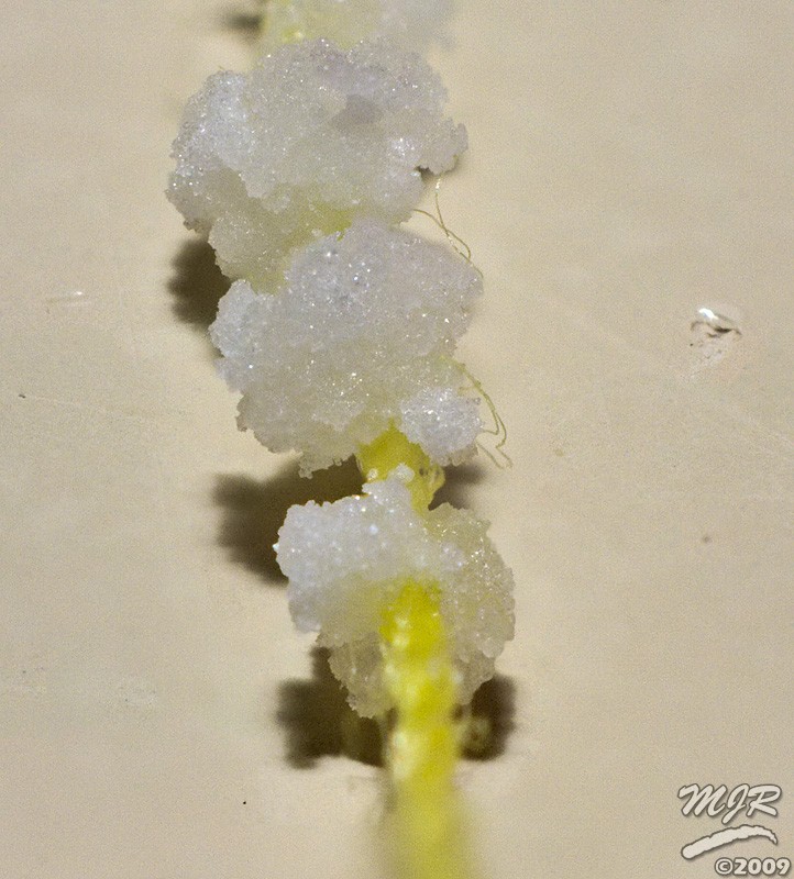
I've wondered about this since I was a kid and tried to grow sugar crystals and salt crystals. Sugar did fine, but I really wanted to see the cool cubes of salt. It didn't work. Recently, I tried to grow salt again, prompted by seeing a huge crystal of salt on the show "How It's Made." So, I set about growing salt, being careful to make sure the pan was clean, the glass was clean, and everything was ideal, even filtering the undissolved crystals through a coffee filter. After about a week, I checked on my project. The results were disappointing to say the least. A few microscopic crystals formed near the surface of the water, and a cauliflower-like mass formed around the pencil suspending the string. Something was seriously wrong. A quick look at the ingredients gives a clue: There are two impurities in the salt; an iodine compound (a necessary nutritional supplement. Most table salt is iodized) and an anti-caking agent. I suspect this is more the culprit than the iodine itself, since the iodine needed is relatively small in relation to the salt. Not only that, but the purpose of the anti-caking compound is to interfere with the salt's ability to build a crystal lattice.


In fact, most salts in the store (even those without the iodine) have some sort of anti-caking agent. Most, but not all. Salt used in the canning process is completely pure. This can be found near the canning jars and lids. After preparing a new solution using this salt, the difference was very apparent. The solution as it cooled formed a film of crystals at the surface, and seemed to be brimming with glinting, brilliant "diamond dust" I filtered the solution and hung my string in this new solution, and set it in a place where it will be relatively undisturbed. Within minutes tiny needles began to form in the water, and sink to the bottom, in a couple hours crystals were already starting to form on the string. Success at last!


The next stage will be to take an ideal specimen from the crystals formed by the solution and attach it to some nylon fishing line to use as a seed for the final large crystal. Stay tuned!