Some shameless promotion of a friend's blog:
Mock Ramblings
He's a writer, and posts some rather clever series. If you haven't read any of his writing, you really should! It's good. Real good. One of my favorite (though they haven't made an appearance recently) is Reflections of a Deranged Cultist. Formatted as hijacked blog postings, the deranged cultist, and no sometimes his love interest make postings about the goings on in a secret Cthulhu worshiping cult. What could be more fun? A steel sphere filled with angry porcu-bats, that's what!
Tuesday, December 20, 2011
Wednesday, December 07, 2011
Lab Notes: Elemental Iodine - wrap up
In my previous experiment I extracted elemental iodine from Tincture of Iodides. Now to explore how it happens.
I knew that the mixture of hydrogen peroxide and hydrochloric acid caused elemental iodine to precipitate from the solution, but didn't understand the mechanism. Now, after a bit of exploring and research, I understand the reaction mechanism.
Starting with what is known:

You can see the potassium is left as a positive ion, as the iodine is no longer combined with it. Also note the Iodine was in the -1 oxidation state, but is now in the 0 oxidation state. This means it has been oxidized, not reduced. So, an oxidizer is needed to move the state up one. Hydrogen peroxide is readily available, and at low concentrations is relatively safe to work with. No oxygen was evolved in the reaction between the hydrogen peroxide and potassium iodide, so what is hydrogen peroxide reduced to?

Water and an oxygen radical? Not quite. I'll get to why in a moment.Since no oxygen is evolved from this reaction, I know that oxygen is not generated, so the hydrogen peroxide must be reduced to water. In order for that to occur, there must be hydrogen ions available to balance the equation. So, this pair of half-reactions is most likely:

Adding an acid allows the hydrogen peroxide to decompose to 2 water molecules. After combining the 2 equations, you obtain this equation:

Which is the mechanism behind the reaction. It is a redox reaction, where the Iodine is oxidized, and the hydrogen peroxide is reduced. In my reaction I used hydrochloric acid, so putting everything together, this is the resulting reactants and products:

As you can see, the result is elemental iodine precipitating out of a solution of potassium chloride.
You can see the potassium is left as a positive ion, as the iodine is no longer combined with it. Also note the Iodine was in the -1 oxidation state, but is now in the 0 oxidation state. This means it has been oxidized, not reduced. So, an oxidizer is needed to move the state up one. Hydrogen peroxide is readily available, and at low concentrations is relatively safe to work with. No oxygen was evolved in the reaction between the hydrogen peroxide and potassium iodide, so what is hydrogen peroxide reduced to?
Water and an oxygen radical? Not quite. I'll get to why in a moment.Since no oxygen is evolved from this reaction, I know that oxygen is not generated, so the hydrogen peroxide must be reduced to water. In order for that to occur, there must be hydrogen ions available to balance the equation. So, this pair of half-reactions is most likely:
Adding an acid allows the hydrogen peroxide to decompose to 2 water molecules. After combining the 2 equations, you obtain this equation:
Which is the mechanism behind the reaction. It is a redox reaction, where the Iodine is oxidized, and the hydrogen peroxide is reduced. In my reaction I used hydrochloric acid, so putting everything together, this is the resulting reactants and products:
As you can see, the result is elemental iodine precipitating out of a solution of potassium chloride.
Tuesday, December 06, 2011
Lab Notes: Iron Oxides
For fun, I had this idea: the classic grade-school experiment: making rust. Good ol' iron oxide. So, I grabbed a small row of staples, added some salt, and dropped them in the water.... and waited.
I'm not the most patient person in the world, so I grew tired of how long it was taking to turn steel into rust. Thinking to myself, "Hydrogen peroxide is an oxidizer, therefore, hydrogen peroxide should make the rust faster", and it did. What I ended up with was iron hydroxide, no iron oxide, but with heat it dehydrates, which yielded the black iron oxide, magnetite. Not surprisingly, it's magnetic and quite fun to play with, but it wasn't what I was after, I wanted the deeply red Iron (III) Oxide. When rust forms, it's a mix of oxides and hydroxides. I was hoping to separate the two by somehow driving one into solution, while leaving the other alone. The idea occurred to me by way of a mistake. I had a vial of what was left over after attempting to get a purer form of acetic acid through heat distillation, instead of grabbing the empty vial, I grabbed that one instead, pouring the magnetic iron oxide into that instead of an empty vial. I noticed that the brown portion was gone, leaving behind only the black. I also noticed that the solution took on a very strong orange coloration. So, I set out to attempt this. Reacted more of the oxide with vinegar (acetic acid), and filtered. To my surprise what came out was a stunningly bright orange solution. What I'm not sure of right now is if it is iron acetate, or iron oxide dissolved in acetic acid. I'm in the process of evaporating the liquid from the solution, and I will see what I get when I rinse the dry product with water.
On another note about the oxidation with hydrogen peroxide, it seems to go much faster with the introduction of sodium chloride (table salt), I don't know the mechanism behind this, but it was very interesting to observe.
Tuesday, November 29, 2011
Lab Notes: Introduction, Element Collecting and Elemental Iodine
First, an introduction to a new feature of this blog: Lab Notes
As a kid, I was very interested in chemistry. I begged and begged for a chemistry set, finally mom and dad relented and purchased a rather nice one. I spent many, many hours doing the experiments with the set. As I got further along, I found a book that had some more advanced chemistry experiments. Many things fascinated me in the book, but they all looked to be a bit complex, but I saw something that seemed simple, and produced an exciting result; a chemistry class classic, the reaction of potassium permanganate and glycerin. Somehow I convinced my mom to procure KMnO3, and the glycerin. I then did the experiment in a tuna tin. Mom was quite shocked at the result. I was quite satisfied with the 1ft high violet flame. I was also hooked.
I dabbled a bit in reading about chemistry online. It was interesting, but was missing the practicality. I'm finally in a situation where I can do a lot of the stuff I've been wanting to do with chemistry. Now I've bought some glassware (as I get into more stuff that could be potentially toxic, I do not want to use my dishes!) and set about with some experimentation. And with that, I realized I need to keep lab notes, hence, the new blog subject: Lab Notes.
A couple of my first experiments were some basic kitchen chemistry, producing sodium acetate out of vinegar and baking soda, concentrating it to the hydrated crystals, and creating a super saturated solution to play with instant crystallization. after a few failures, I had some success, but the product was impure and rather finicky, but did get the instant crystallization I was looking for. I wanted more, and I had been watching a lot of YouTube videos, and found an interesting one to try. It required hydrochloric acid (available at any hardware store as muriatic acid) and hydrogen peroxide. Essentially extracting the bismuth metal from Pepto-Bismol. I haven't done this one yet, but I am planning it. I experimented with a small amount of the HCl and aluminum metal, which dissolved the metal to make a solution of aluminum chloride. It really wasn't surprising and totally expected, also expected was the exothermic nature of the reaction, I was careful to only add small amounts of aluminum at a time to prevent it from heating the plastic cup too much and causing a nasty spill. I eventually moved this outside because of the HCl fumes.
One of my hobbies which started a couple of years ago and inspired by Theodore Gray is the practice of element collecting. I started with coins stamped in various metals (I will one day photograph the coins and share them here), there are elements that aren't currently available as a coin. I added mercury to my collection by harvesting the small glass ampoule from an old thermostat, but aside from the coins (which are most of the transition metals, alkali earth metals, rare-earth metals and some of the non-metals) I was still short on my collection. I wanted more, especially the alkali metals and halides. Neither of which companies are willing to ship due to the reactivity. This is part of the reason for my desire to get chemistry gear, and start doing some home chemistry. The other reason is to investigate was of purifying various substances, such as acetic acid from vinegar, sodium acetate, and so on. I also wanted the lab gear for another hobby of mine: electronics, which to make printed circuits requires some etching chemicals which are rather nasty, toxic and corrosive. I wanted proper handling for these reagents, rather than using something that could potentially be confused with kitchenware.
The iodine was then transferred to a small vial and heated to verify that it was indeed iodine, the purple vapor indicated it was what I wanted it to be.
So, now i have a vial of iodine to add to my element collection.
As a kid, I was very interested in chemistry. I begged and begged for a chemistry set, finally mom and dad relented and purchased a rather nice one. I spent many, many hours doing the experiments with the set. As I got further along, I found a book that had some more advanced chemistry experiments. Many things fascinated me in the book, but they all looked to be a bit complex, but I saw something that seemed simple, and produced an exciting result; a chemistry class classic, the reaction of potassium permanganate and glycerin. Somehow I convinced my mom to procure KMnO3, and the glycerin. I then did the experiment in a tuna tin. Mom was quite shocked at the result. I was quite satisfied with the 1ft high violet flame. I was also hooked.
I dabbled a bit in reading about chemistry online. It was interesting, but was missing the practicality. I'm finally in a situation where I can do a lot of the stuff I've been wanting to do with chemistry. Now I've bought some glassware (as I get into more stuff that could be potentially toxic, I do not want to use my dishes!) and set about with some experimentation. And with that, I realized I need to keep lab notes, hence, the new blog subject: Lab Notes.
First experiments
A couple of my first experiments were some basic kitchen chemistry, producing sodium acetate out of vinegar and baking soda, concentrating it to the hydrated crystals, and creating a super saturated solution to play with instant crystallization. after a few failures, I had some success, but the product was impure and rather finicky, but did get the instant crystallization I was looking for. I wanted more, and I had been watching a lot of YouTube videos, and found an interesting one to try. It required hydrochloric acid (available at any hardware store as muriatic acid) and hydrogen peroxide. Essentially extracting the bismuth metal from Pepto-Bismol. I haven't done this one yet, but I am planning it. I experimented with a small amount of the HCl and aluminum metal, which dissolved the metal to make a solution of aluminum chloride. It really wasn't surprising and totally expected, also expected was the exothermic nature of the reaction, I was careful to only add small amounts of aluminum at a time to prevent it from heating the plastic cup too much and causing a nasty spill. I eventually moved this outside because of the HCl fumes.
Element collecting
One of my hobbies which started a couple of years ago and inspired by Theodore Gray is the practice of element collecting. I started with coins stamped in various metals (I will one day photograph the coins and share them here), there are elements that aren't currently available as a coin. I added mercury to my collection by harvesting the small glass ampoule from an old thermostat, but aside from the coins (which are most of the transition metals, alkali earth metals, rare-earth metals and some of the non-metals) I was still short on my collection. I wanted more, especially the alkali metals and halides. Neither of which companies are willing to ship due to the reactivity. This is part of the reason for my desire to get chemistry gear, and start doing some home chemistry. The other reason is to investigate was of purifying various substances, such as acetic acid from vinegar, sodium acetate, and so on. I also wanted the lab gear for another hobby of mine: electronics, which to make printed circuits requires some etching chemicals which are rather nasty, toxic and corrosive. I wanted proper handling for these reagents, rather than using something that could potentially be confused with kitchenware.
Preparing Elemental Iodine
So, at Walmart, I was purchasing hydrogen peroxide for the bismuth experiment, when I spotted a tiny brown bottle: Tincture of Iodine! The first thought that ran through my head was elemental iodine. So I bought it and brought it home with me. Last night, while catching up on Youtube, I came across a video, coincidentally, which explained how to isolate the iodine from the tincture. It was simple, and used chemicals and items I already had, so off I went. That's when I noticed something disheartening: It was not tincture of iodine, but tincture of iodides. Hmm. I remember seeing a video on how to extract iodine from potassium iodide (which this contained, along with ethanol, ammonia(!), and ammonium iodide) Ok, so its the same procedure, just a different starting point. No big deal, the ammonia however posed a problem: Iodine reacts with ammonia to produce nitrogen triiodide, which is a contact explosive. I can't have that! So, I started with tiny amounts of everything. a couple ml of the tincture, HCl and hydrogen peroxide. This way, If I do make the nitrogen triiodide accidentally, it will be a small enough quantity that it can be easily dealt with. So, I begin pouring the HCl into the beaker, and (with a bit of dread) noticed it start to fume as I brought the beaker over the one that contained the tincture. Oh, no... not HCl vapors again. I'll have to go out in the cold to finish it. It then occurred to me: I have 2 substances which are giving off a gas, HCl and ammonia. the two combine to form ammonium chloride, the substance of a smoke! This also allayed one of my fears, the HCl would react away the ammonia and prevent the triiodide from being produced. This was good, so I finished the reaction, and proceeded to filter the iodine precipitated from the reaction.The iodine was then transferred to a small vial and heated to verify that it was indeed iodine, the purple vapor indicated it was what I wanted it to be.
So, now i have a vial of iodine to add to my element collection.
Sunday, June 20, 2010
Bypassing the Property Grid's Sort Order
While working on a programming project one of the things I wanted to include was the ability to list out the values in the collection in the same way the array lists its items.
Normally, the collection displays an ellipsis button, allowing the user to manipulate the collection, but does not allow the user to expand the list of items like an array does. I figured this would be very simple to add. The .NET framework provides a base class for an object called a TypeConverter. The TypeConverter allows objects of various types to be translated to and from various representations.
Beyond that, the TypeConverter can supply a list of standard values (Enumerators use this, which allows the property grid to display a drop-down list containing the various valid values.) The TypeConverter can also supply an editor class for the type (You see this in form designers all the time, the font dialog, the drop-down for colors, the drop-down for for docking, etc...) Finally, the type converter can also supply a list of properties that the object can display as child properties of a property. It is this that I will focus on:
 Far from optimal for dealing with a list of items. The list is sorted alphabetically. But arrays seem to sort by index. That was what I wanted, so I began spelunking through the reference source code of the .NET framework. Examining the Array code and ArrayConverter code revealed nothing. They were doing essentially what I was doing. I then explored the grid. It appears the PropertyGrid itself considers an array a special case and sorts the items by index. That is no use to me.
The following listing shows the ListPropertyDescriptorCollection class that does the magic:
Normally, the collection displays an ellipsis button, allowing the user to manipulate the collection, but does not allow the user to expand the list of items like an array does. I figured this would be very simple to add. The .NET framework provides a base class for an object called a TypeConverter. The TypeConverter allows objects of various types to be translated to and from various representations.
Beyond that, the TypeConverter can supply a list of standard values (Enumerators use this, which allows the property grid to display a drop-down list containing the various valid values.) The TypeConverter can also supply an editor class for the type (You see this in form designers all the time, the font dialog, the drop-down for colors, the drop-down for for docking, etc...) Finally, the type converter can also supply a list of properties that the object can display as child properties of a property. It is this that I will focus on:
public override bool GetPropertiesSupported(ITypeDescriptorContext context)
{
return true;
}
public override PropertyDescriptorCollection GetProperties(ITypeDescriptorContext context, object value, Attribute[] attributes)
{
List<String> lst = (List<String>)value;
ListItemDescriptor[] props = new ListItemDescriptor[lst.Count];
for (int i = 0; i < lst.Count; i++)
props[i] = new ListItemDescriptor(i);
return new PropertyDescriptorCollection(props);
}
{
return true;
}
public override PropertyDescriptorCollection GetProperties(ITypeDescriptorContext context, object value, Attribute[] attributes)
{
List<String> lst = (List<String>)value;
ListItemDescriptor[] props = new ListItemDescriptor[lst.Count];
for (int i = 0; i < lst.Count; i++)
props[i] = new ListItemDescriptor(i);
return new PropertyDescriptorCollection(props);
}
The above code demonstrates how the properties are provided by the TypeDescriptor. Using the above code results in the following list in the grid:

Using the sort method of the PropertyDescriptorCollection object does nothing, since the grid will always override it with the user's sort preference. So, how to sort the items by index?
The secret is in the property descriptor collection. Replacing the return statement above with the following:
return new ListPropertyDescriptorCollection(props);
The following listing shows the ListPropertyDescriptorCollection class that does the magic:
private class ListPropertyDescriptorCollection : PropertyDescriptorCollection
{
public ListPropertyDescriptorCollection(PropertyDescriptor[] props)
: base(props)
{
}
public override PropertyDescriptorCollection Sort
(System.Collections.IComparer comparer)
{
if (comparer.GetType().Name == "DisplayNameSortComparer")
{
ListItemDescriptor.ListItemDescriptorSortComparer comp =
new ListItemDescriptor.ListItemDescriptorSortComparer();
return Sort(comp);
}
else
{
return base.Sort(comparer);
}
}
}
{
public ListPropertyDescriptorCollection(PropertyDescriptor[] props)
: base(props)
{
}
public override PropertyDescriptorCollection Sort
(System.Collections.IComparer comparer)
{
if (comparer.GetType().Name == "DisplayNameSortComparer")
{
ListItemDescriptor.ListItemDescriptorSortComparer comp =
new ListItemDescriptor.ListItemDescriptorSortComparer();
return Sort(comp);
}
else
{
return base.Sort(comparer);
}
}
}
The code that performs the trick should be rather self-evident:
ListItemDescriptor.ListItemDescriptorSortComparer comp = new ListItemDescriptor.ListItemDescriptorSortComparer();
return Sort(comp);
return Sort(comp);
Two lines of code in this function do all that is necessary to force the numeric sort. The comparer in this case compares the indicies of the descriptors, causing the sort function to sort by the numeric index. This completely replaces any sort function used with the desired sort, thereby forcing a sort by index.


Wednesday, June 02, 2010
Building a CPU - Stalled
I'm currently stalled on the CPU project, mainly switching focus to writing my own logic simulation program with the hopes of bringing this project into a program that's a bit easier to use.
I've still be mulling over the program counter update issue and why it isn't syncing, but I just haven't given myself much time with that.
I've still be mulling over the program counter update issue and why it isn't syncing, but I just haven't given myself much time with that.
Wednesday, May 19, 2010
Building a CPU - Following instructions
Well, my first run through on the simulator with memory and a few instructions worth of microcode and... well, hmmmm.
The instructions seem to work fine until the instruction terminates, and goes back to the fetch instruction, then things fall apart. For some reason, the program counter doesn't seem to be advancing right, or the flip-flops holding each 4-bit word don't seem to be getting the appropriate instruction at the appropriate time.
I'm going to need to do some more experimentation and thought on this one to figure out what went wrong. I have a feeling what I really need to do us use latches instead of flip-flops. More things to play around with. It may make sense to make the registers D-Latches as well, so data is written instantaneously, rather than on a clock tick. Another possibility is using more than one clock, possibly by using some sort of delay line or a secondary clock source.
Monday, May 17, 2010
Building a CPU - Musings on the evolution of machine code
Over the weekend I got deeper into some of the more thorny parts of the design. The ALU was really rather simple. For the most part the glue logic was pretty simple. Sure, it looks big and complex, but it's mostly just a bunch of wires that connect from point a to a central routing station to point b, oh, and a few dozen control signals to tell the thing what to do.
This is all fine and good. I can by setting a certain set of inputs instruct the machine to take register o, connect it to bus b on ALU and add it to the accumulator. Great, so the basis of instructions will work.
Now, all I need to do is create an instruction set. At first I had the brilliant idea of using the most significant five bits (8 bit instructions, 2 words) This created a very nice set of 8 bit instructions. I started working out the machine code, how the arguments will be handled and how op-code+arguments will be structured. I knew I was going to somehow index into a set of EEPROMs to get the signals, or a series of signals the op-code will generate. Essentially the EEPROMs would store a table. After fidgeting around with the op-codes and their respective arguments for a while it became painfully apparent that I would either have more ROM for instruction microcode than the entire system has addressable space or I would need some very complex decoding logic to get an index into the appropriate entry into the table.
That simply was not going to work. First, it seems wrong to have several more times address space just to store instructions than the chip is capable of handling from the external world, not only that, but it would be exceptionally sparse, a huge waste of memory. Yes-- memory is cheap these days. ROM is not as cheap, but still rather cheap. The other alternative would mean I'd need a heap of TTL chips to build just the instruction decoder, which aside from requiring large piles of money would also require more power than I care to deal with (I don't really care for needing to add special high-current breakers to the breaker panel, and I don't think the apartment complex would appreciate it.)
So, something had to give. I tried squeezing some different kinds of flags into those eight bits. Hmm, no, that still doesn't work out as cleanly as I would like. I Finally broke down and decided the op-codes between instruction forms will only loosely be related. This means, for example, ld (load a register from memory or another register) would take up about half the available slots, due to the fact that it necessarily needs to move data from anywhere to almost anywhere. st (store register data to memory) is a little bit better in this regard, since the destination is only memory.
Which leaves me with machine code that is functional, but not the orthogonal work of art I had hoped for.
The next challenge was getting some microcode in the simulation to test things out. Unfortunately the banked layout makes things rather nasty as far as just jumping into the sim's hex editor and plopping in codes (notwithstanding the fact that the control word is long enough to tax my memory of what bit handles what, despite the logical ordering of things.) This necessitates some sort of assembler, so I have begun a quick-and-dirty assembler for microcode. This is unlike any other assembly code, the microcode is highly parallel, and needs to perform several operations at once. So each "instruction" becomes a list of instructions followed by either a fetch or next. Fetch will of course read 2 words from the data bus and latch a new instruction. Next will increment an internal counter in the microcode sequencer. As it stands now, each instruction can perform 16 microcode steps. This is, obviously, subject to change as I get a better grip on the requirements of each instruction. 16 seems generous. Some of the instructions in the micro-assembler, will really be a composite of signals, some will be individual signals. Some will simply be modifiers.
I also knew that some of the instruction forms, especially in the forms [si+c], [si+oac], [si+<imm>], [si+<imm16>] would need a bit of new logic in the address bus control, since I didn't think to add the ability to combine addresses with external numbers. This also grows the control word by a few more signals.
I am very glad to be running this through a simulator before beginning the build. It allows me to catch flaws in my design and plan before wiring things up. Before simulations, I'd need to put the whole thing on a breadboard and test it out. Sure, not horrible, but definitely not as quick.
This is all fine and good. I can by setting a certain set of inputs instruct the machine to take register o, connect it to bus b on ALU and add it to the accumulator. Great, so the basis of instructions will work.
Now, all I need to do is create an instruction set. At first I had the brilliant idea of using the most significant five bits (8 bit instructions, 2 words) This created a very nice set of 8 bit instructions. I started working out the machine code, how the arguments will be handled and how op-code+arguments will be structured. I knew I was going to somehow index into a set of EEPROMs to get the signals, or a series of signals the op-code will generate. Essentially the EEPROMs would store a table. After fidgeting around with the op-codes and their respective arguments for a while it became painfully apparent that I would either have more ROM for instruction microcode than the entire system has addressable space or I would need some very complex decoding logic to get an index into the appropriate entry into the table.
That simply was not going to work. First, it seems wrong to have several more times address space just to store instructions than the chip is capable of handling from the external world, not only that, but it would be exceptionally sparse, a huge waste of memory. Yes-- memory is cheap these days. ROM is not as cheap, but still rather cheap. The other alternative would mean I'd need a heap of TTL chips to build just the instruction decoder, which aside from requiring large piles of money would also require more power than I care to deal with (I don't really care for needing to add special high-current breakers to the breaker panel, and I don't think the apartment complex would appreciate it.)
So, something had to give. I tried squeezing some different kinds of flags into those eight bits. Hmm, no, that still doesn't work out as cleanly as I would like. I Finally broke down and decided the op-codes between instruction forms will only loosely be related. This means, for example, ld (load a register from memory or another register) would take up about half the available slots, due to the fact that it necessarily needs to move data from anywhere to almost anywhere. st (store register data to memory) is a little bit better in this regard, since the destination is only memory.
Which leaves me with machine code that is functional, but not the orthogonal work of art I had hoped for.
Control logic: Easy at first but maybe not on closer inspection
So I began work on the instruction decoder after I put together an instruction set. One of the things I knew would be a requirement is that the EEPROMs be banked. Allow me to explain: The control word is ~50 bits wide. Each micro-instruction is a control word. EEPROMs generally have an 8 bit data bus. I could fetch in series each chunk of microcode and bring it into a final register, but this complicates things and wastes precious instruction cycles. So, rather than a single EEPROM, I'll need 7. As far as the decoder is concerned, it's not a big deal. The tricky part is getting an 8 bit instruction from a 4 bit data bus. This has to be done in two cycles. Also, during this cycle the current micro-instruction must stay the same, or the decoder could lose its fetch signal. So, the decoder pulls an op-code in two cycles, and once the cycle is complete it then latches the op-code. Upon latching, the first micro-instruction of that op-code now sends its signals out to the rest of the CPU. That latch step added one clock to the fetch cycle. A necessary evil, I suppose.The next challenge was getting some microcode in the simulation to test things out. Unfortunately the banked layout makes things rather nasty as far as just jumping into the sim's hex editor and plopping in codes (notwithstanding the fact that the control word is long enough to tax my memory of what bit handles what, despite the logical ordering of things.) This necessitates some sort of assembler, so I have begun a quick-and-dirty assembler for microcode. This is unlike any other assembly code, the microcode is highly parallel, and needs to perform several operations at once. So each "instruction" becomes a list of instructions followed by either a fetch or next. Fetch will of course read 2 words from the data bus and latch a new instruction. Next will increment an internal counter in the microcode sequencer. As it stands now, each instruction can perform 16 microcode steps. This is, obviously, subject to change as I get a better grip on the requirements of each instruction. 16 seems generous. Some of the instructions in the micro-assembler, will really be a composite of signals, some will be individual signals. Some will simply be modifiers.
I also knew that some of the instruction forms, especially in the forms [si+c], [si+oac], [si+<imm>], [si+<imm16>] would need a bit of new logic in the address bus control, since I didn't think to add the ability to combine addresses with external numbers. This also grows the control word by a few more signals.
I am very glad to be running this through a simulator before beginning the build. It allows me to catch flaws in my design and plan before wiring things up. Before simulations, I'd need to put the whole thing on a breadboard and test it out. Sure, not horrible, but definitely not as quick.
Thursday, May 13, 2010
Building a CPU - The beginning
So I got the brilliant idea to build a CPU from scratch. So, I'm well into the design phase of this project now, and have a pretty good start. I've designed the ALU, and have some of the control circuitry done.

The diagram above shows the ALU circuitry. Bus A and Bus B serve as the inputs. The shifter can only accept input from bus a, the complementor can accept inputs from either bus. All feed into the result bus, additionally the complementor can feed into the second argument of the adder.
The ALU is capable of performing logic functions (AND, OR, XOR) complementation (NOT, and two's complement) shifting, rotating and addition. Other operations will need to be composites of existing operations. The shifter can shift, rotate, shift with a carry in, and rotate through carry. The flags unit determines which of the 4 flag bits should be active. Results will be placed on the results bus.
Multiplication and division are not available in the ALU, but could be emulated in software using shifts and addition. The ALU also works on signed values, and the shifter can be set to sign extend or not. With signed values subtraction becomes simple addition.
Below is the control circuit. This is not complete as of yet, but may give some insight into how it all works together.

You'll notice it all looks overwhelmingly complex. It isn't really. There are a ton of control lines to direct the ALU what to do, control the registers, and control where the data goes. Unfortunately, the simulation software doesn't allow for sub circuits to have pins that serve as both an input and an output, so there are double the lines on the circuit. You can see that the address bus is 16 bits wide, and the data bus is 4 bits wide.
The CPU has the following registers: Four Bit: A (Accumulator), O (Operand) FLAGS, C (Counter), 16 bit: PC (Program Counter), SI, DI (source and destination addresses). Additionally, there are two registers for the stack. These combine on the data bus to form a 16 bit address, SP and BP. BP is four bits wide, SP is 12 bits wide. This allows for 4k of stack. The placement of the stack is restricted to 4k boundaries, but the BP register allows some flexibility in the placement of the stack, depending on how external memory is configured. The control word will come from a microcode sequencer.
Some of this design is likely to change, and there are some mistakes. the ALU should only be wired to accept input from the accumulator and another register, and will output to a temporary holding latch, which will then store the value in the register. This means the basic operations can complete in two clock cycles. As the diagram is now, it does not function. The data bus controller can only direct data from once source to one destination, and both of the ALU busses are connected to this controller.
Sunday, January 24, 2010
Growing Crystals = Fail
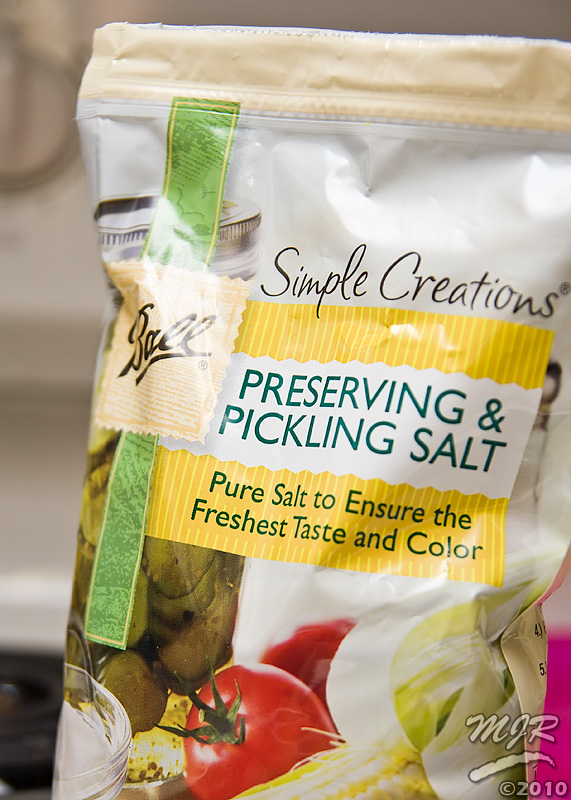
 Lets say for a moment you and your kids decide to do a science experiment. You want to grow crystals. Great! There are lots of resources out there that tell you how to do all sorts of crystals. One of which is salt. Ordinary Table Salt.
So you and your family set out to grow beautiful cubic crystals. You heat up some water, and dump tons of salt in the water until nothing will dissolve anymore. You pour your supersaturated solution of good old sodium chloride into a cup, and dangle a string in the cup. You wait..... and wait... and wait. A week passes, and you have nothing to show for it at all. The sugar crystals came out great, but sugar is so pedestrian. The cubic salt crystals would have been so much better, but it's a total no-go. What happened?
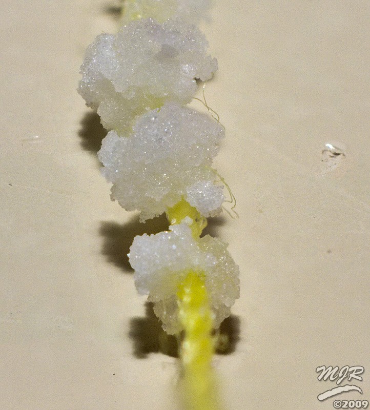

The next stage will be to take an ideal specimen from the crystals formed by the solution and attach it to some nylon fishing line to use as a seed for the final large crystal. Stay tuned!

Subscribe to:
Comments (Atom)